Description
This push button relay is used to open and close circuits by receiving signals from an underwater Tap Switch. It can be used as the switch of small and medium power supply.
It can be used with the Tap switch to turn the Tap switch into a self-locking switch, adding self-locking function and long-press shutdown anti-false-touch function to it. When the switch is pressed (30ms fixed dithering time), the relay is energized, and when the switch is long pressed (1 second), the relay is turned off.
The light on the board corresponds to the closed or open state of the relay, with a signaling indicator port.
Shipping List
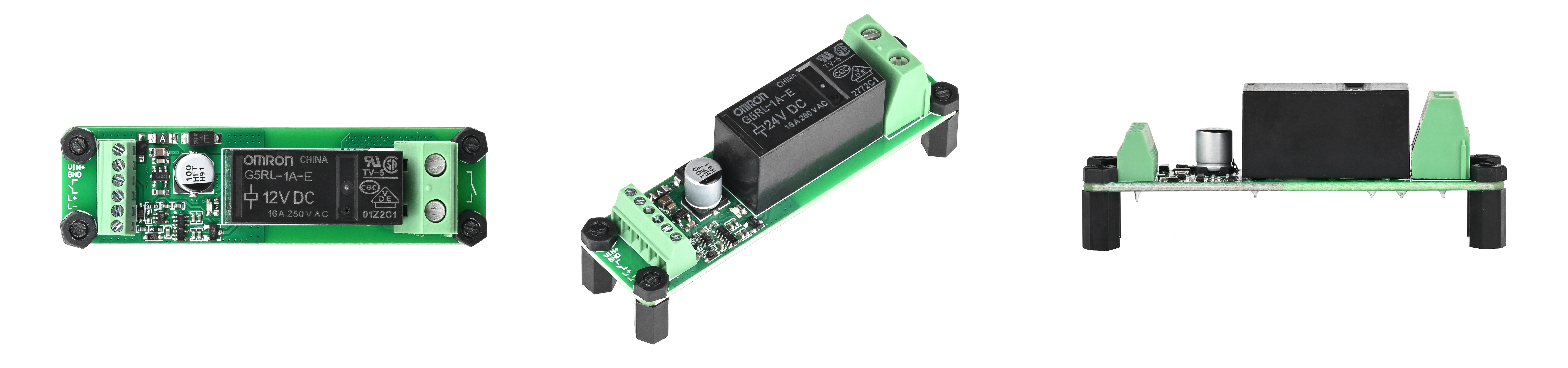
- 1 × Push Button Relay
- 1 set × Plastic Screw Posts
Specifications
| Item | SKU | Relay Model | Weight |
|---|---|---|---|
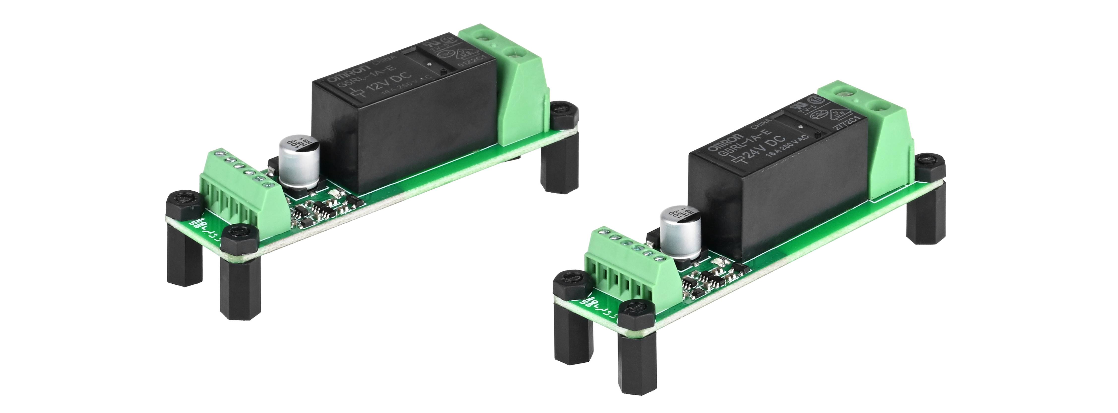
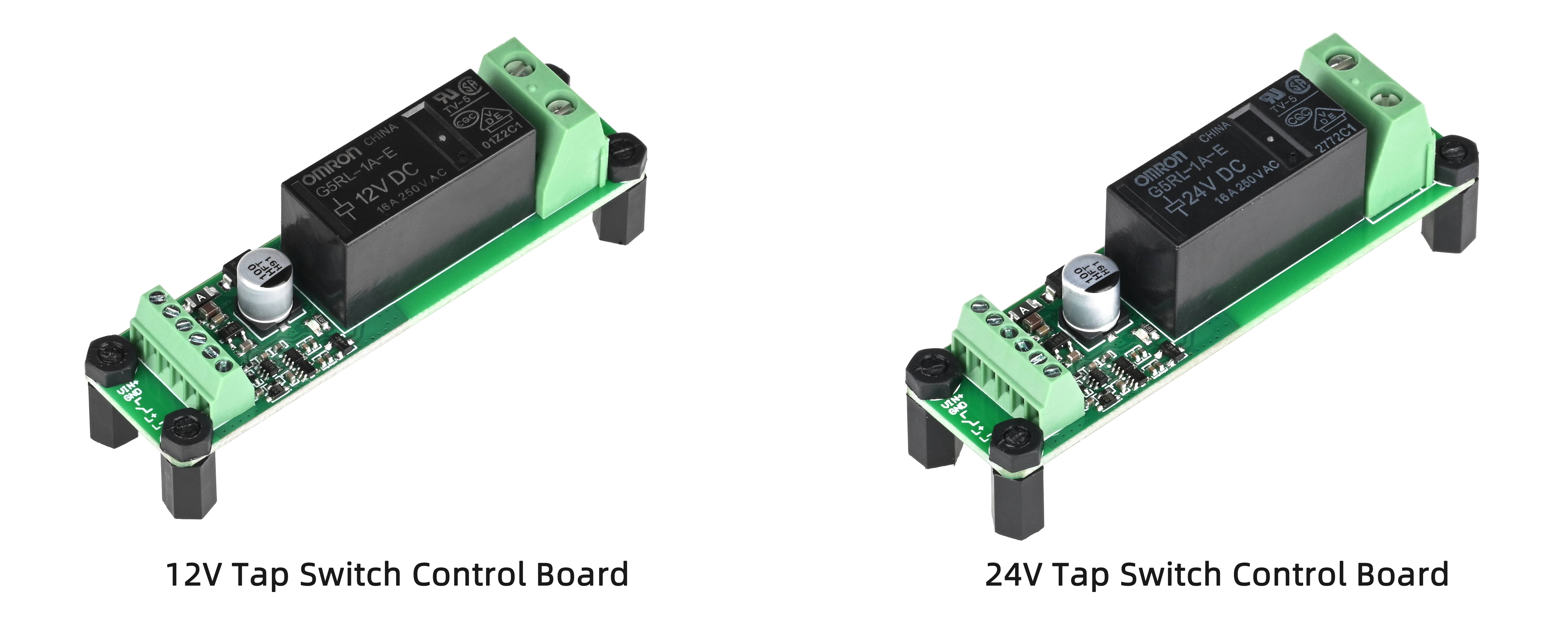
| 12V Push Button Relay | 12020605-0012 | G5RL-1A-E DC12V | Approx. 22g |
| 24V Push Button Relay | 12020605-0024 | G5RL-1A-E DC24V | Approx. 22g |
| Item | 12V Push Button Relay | 24V Push Button Relay |
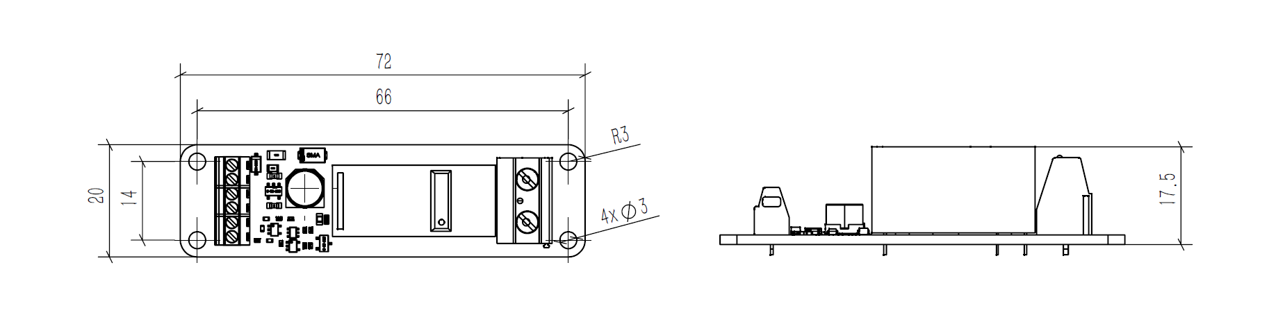
| Dimension | 72*20mm | 72*20mm |
| Height | 20 | 20 |
| Mounting Hole Distance | 14 x 66 | 14 x 66 |
| Mounting Hole Size | 3 | 3 |
| Supply Voltage | 3S Battery (9.6V-12.6V) | 6S Battery (19.2V-25.2V) |
| Rated Current | 50mA | 30mA |
| Quiescent Current | 12µA | 14µA |
| Button Debounce Time | 30ms | 30ms |
| Turn- off with Long Press | 1S | 1S |
| Rated Load | AC250V 16A;DC24V 16A | AC250V 16A;DC24V 16A |
| Maximum Switching Current | 16A | 16A |
| Contact Type | SPST-NO (1a) | SPST-NO (1a) |
| Contact Resistance | Below 100mΩ | Below 100mΩ |
| Action/ Reset Time | Below 15ms | Below 15ms |
Guides
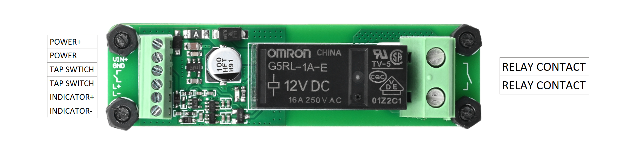
Connecting Diagram:
PCB Dimension:
Precautions for use:
● When a DC power supply with fluctuations is included, please use a power supply with fluctuations below ± 5%. If the fluctuation of the coil current becomes larger, the operating voltage will change greatly, and a buzzer will also be emitted.
● If the voltage applied to the coil is insufficient, the relay does not operate or the operation is unstable, resulting in reduced contact life, welding and other contact failures.
● Drop or impact may result in false triggering and damage to the relay.
● When the relay is powered on, there is a risk of electric shock by touching the charging part.
● Maximum current on contact switch. Due to the influence of electromagnetic energy stored in inductive loads, the switching capacity of inductive loads is usually lower than that of resistive loads. When the load is inductive, use appropriate surge suppression.
According to the actual circuit, the actual load under the actual conditions of use.
Load type and inrush current:
Differences in the type of load will result in different inrush currents when the relay is engaged.
| Load Type | Inrush Current |
| Resistive Load | 1 time of steady-state current |
| Motor Load | 5~10 times of steady-state current |
| Capacitor Load | 20~40 times of steady-state current |
Wire Diameter:
The diameter of the conductor should be determined by the load current. If the wire is thin, it will burn out due to abnormal heating of the wire.
| Permissible Current (A) | Cross-sectional Area (mm²) |
| 6 | 0.75 |
| 10 | 1.25 |
| 15 | 2 |
| 20 | 3.5 |
FAQ
● Is it necessary to supply a separate operating power supply to the circuit board when converting the tap switch to self-locking use?
A separate power supply for the circuit board is required. Power can be supplied directly from a battery.
● What types of switches can be connected?
Self-resetting tap switches.
● What is the difference between the MOS electronic switch board and the relay?
There is no leakage current when the relay is open. The coil section is completely insulated from the contact section and is relatively independent of the circuit.